
Home > Products > Integrated Stepper Servo Motors > Pulse Integrated Stepper Servo Motors
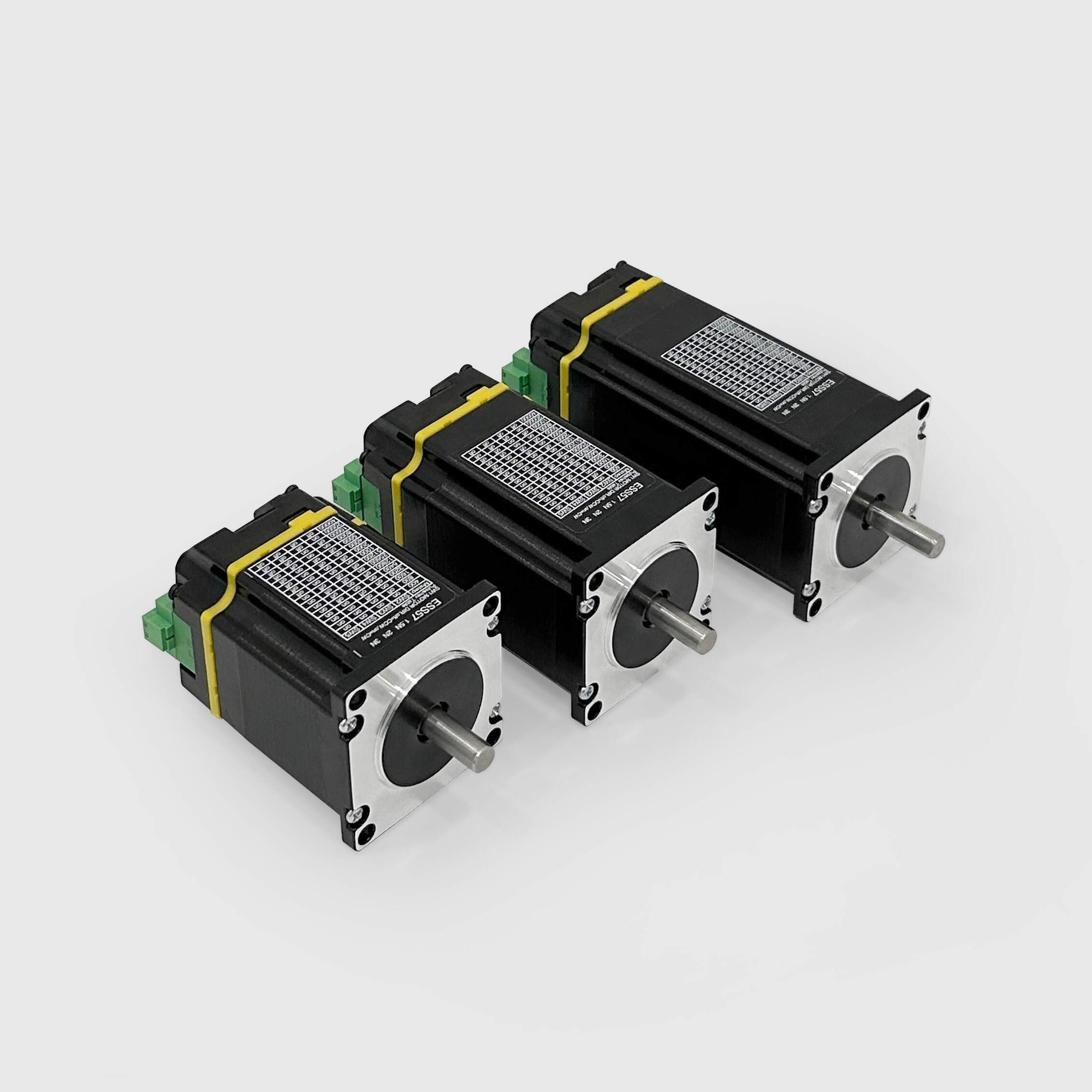
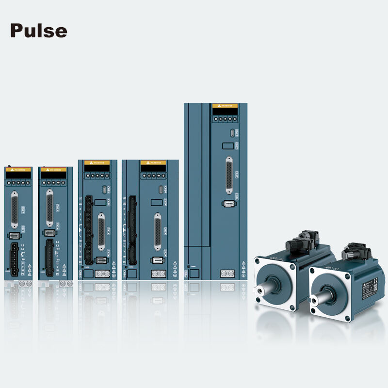
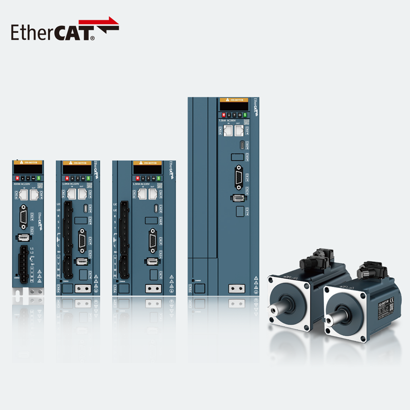
ESS57 is a new type of integrated motor drive hybrid servo system with communication capabilities. It uses advanced 32-bit high-performance ARM chips and closed-loop control technology to prevent step loss, ensuring product accuracy; the high-speed torque decay is much lower than that of traditional open-loop drivers, significantly enhancing the high-speed performance and torque of stepper motors; it employs load-based current control technology, effectively reducing motor temperature rise and extending motor life; it includes built-in alarm output signals for easy monitoring and control by the host computer; the position out-of-tolerance alarm function ensures safe operation of processing equipment. It is an ideal upgrade from traditional open-loop stepper drives and can replace some traditional AC servo systems at a price only 50% of that of AC servo systems.
1.Features
2.Electrical specifications
Model No. |
Step Angle |
Motor Length |
Current /Phase |
Resistance /Phase |
Inductance /Phase |
Holding Torque |
( °) |
(L)mm |
A |
Ω±10% |
mH±20% |
N.m |
|
|
ESS57-15
|
1.8 |
56 |
4.2 |
0.4
|
1.2 |
1.2 |
|
ESS57P-20
|
1.8 |
76 |
4 |
0.45 |
1.6 |
1.8 |
|
ESS57P-30
|
1.8 |
112 |
4.2 |
0.8 |
3.6 |
3 |
3.Electrical indicators
Power supply |
DC24~48V, recommended power supply DC36V |
Output current |
Peak 6.0A ((current varies with load) |
Logic input current |
7~16mA, recommended 10mA |
Pulse frequency |
0~200KHz |
Encoder line number |
1000 |
Insulation resistance |
≥500MΩ |
4.Usage environment and parameters
Cooling method |
Natural cooling or external radiator |
|
Use environment |
Use occasion |
Try to avoid dust, oil and corrosive gases |
Temperature |
0~40℃ |
|
Humidity |
40~90%RH |
|
Vibration |
5.9m/s2Max |
|
Storage temperature |
-20℃~80℃ |
|
5.Interface definition
(1)Power input port
Terminal number |
Symbol |
Name |
Explain |
1 |
+Vdc |
Positive terminal of DC power supply |
DC+24V~48V Recommended DC+36V power supply |
2 |
GND |
DC power supply ground |
(2)Control signal port
Terminal number |
Symbol |
Name |
Description |
1 |
PUL+ |
Pulse positive input |
Support 5~24V |
2 |
PUL- |
Pulse negative input |
|
3 |
DIR+ |
Direction Positive input |
|
4 |
DIR- |
Direction Negative input |
|
5 |
EN+ |
Enable positive input |
|
6 |
EN- |
Enable negative input |
|
8 |
AL+ |
The alarm signal is being output |
The OC door output has an alarm signal for the default closed indicator, and no alarm signal for the open indicator. |
9 |
AL- |
Negative output of alarm signal |
(3)Status indication
PWR: Power indicator light. When powered on, the green indicator light is on.
ALM: Fault indicator light. Red light flashes once within 3 seconds: over current or phase short circuit fault; red light flashes twice continuously within 3 seconds: over voltage fault; red light flashes seven times continuously within 3 seconds: position error exceeds the limit alarm.
6.DIP switch setting
ESS57 The six-bit code switch is used to set the filter time, motor rotation direction and subdivision accuracy.
SW1, motor rotation direction setting. on=CW, off=CCW.
SW2, SW3, SW4, SW5: subdivision setting.
Steps / circle |
SW2 |
SW3 |
SW4 |
SW5 |
400 |
ON |
ON |
ON |
ON |
800 |
OFF |
ON |
ON |
ON |
1600 |
ON |
OFF |
ON |
ON |
3200 |
OFF |
OFF |
ON |
ON |
6400 |
ON |
ON |
OFF |
ON |
12800 |
OFF |
ON |
OFF |
ON |
25600 |
ON |
OFF |
OFF |
ON |
51200 |
OFF |
OFF |
OFF |
ON |
1000 |
ON |
ON |
ON |
OFF |
2000 |
OFF |
ON |
ON |
OFF |
4000 |
ON |
OFF |
ON |
OFF |
5000 |
OFF |
OFF |
ON |
OFF |
8000 |
ON |
ON |
OFF |
OFF |
10000 |
OFF |
ON |
OFF |
OFF |
20000 |
ON |
OFF |
OFF |
OFF |
40000 |
OFF |
OFF |
OFF |
OFF |
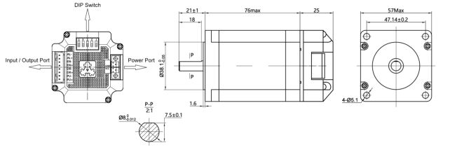
7.Overall Dimensions
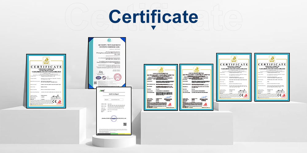
8.Certificate
We have passed the ISO-9001 quality certification system and obtained a number of application patents. Our products have international certifications such as CE and ROHS.
9.Review

Copyright © 2026 Changzhou Jinsanshi Mechatronics Co., Ltd. All rights reserved. - Privacy policy