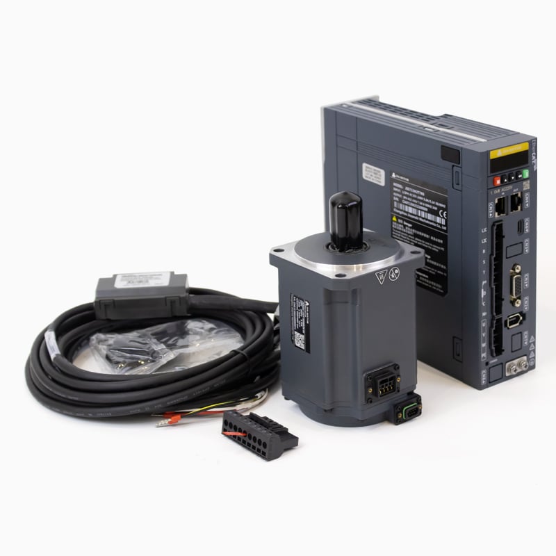
In modern industrial automation, precision and responsiveness are not optional — they are the baseline expectation. At the heart of nearly every high-performance machine axis lies a coordinated system built around servo motors and drives. Understanding how these two components interact is essential for engineers, system integrators, and procurement professionals who need reliable, repeatable motion in their equipment.
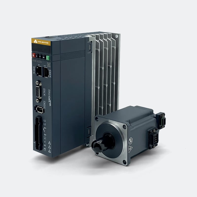
The relationship between servo motors and drives is not simply a matter of one powering the other. It is a tightly coupled feedback architecture where the drive continuously interprets real-time data from the motor and adjusts its output accordingly. This article breaks down the mechanism behind that relationship, explains how the two components divide their responsibilities, and clarifies why their integration is what makes closed-loop motion control so effective across demanding industrial applications.
The Fundamental Roles of Servo Motors and Drives
What the Servo Motor Actually Does
The servo motor is the mechanical output device in the system. It converts electrical energy into precise rotational or linear motion. Unlike standard induction motors, servo motors are designed with low rotor inertia, high torque density, and tight mechanical tolerances that allow them to respond quickly to changing command signals.
Embedded within the servo motor is a feedback device — most commonly an encoder or resolver. This sensor continuously measures the motor shaft's actual position, velocity, and sometimes torque. That data is not used by the motor itself; it is transmitted back to the drive in real time, forming the foundation of closed-loop control.
In servo motors and drives systems, the motor's job is to execute commands faithfully and report its actual state accurately. The quality of the encoder directly affects how precisely the drive can correct errors, which is why high-resolution encoders — such as 17-bit absolute encoders — are standard in precision-grade servo kits.
What the Servo Drive Actually Does
The servo drive is the intelligence layer of the system. It receives a target command — typically a position, velocity, or torque setpoint — from a higher-level controller such as a PLC or motion controller. It then compares that command against the real-time feedback arriving from the motor's encoder.
Based on the difference between the commanded value and the actual measured value, the drive calculates a corrective output and adjusts the current delivered to the motor windings. This calculation happens thousands of times per second, which is what gives servo motors and drives their characteristic responsiveness and accuracy.
The drive also handles power conversion, taking incoming AC or DC supply voltage and converting it into the precise variable-frequency, variable-amplitude waveform the motor needs at any given moment. It manages acceleration ramps, deceleration profiles, and fault protection — making it far more than a simple amplifier.
The Closed-Loop Feedback Mechanism Explained
How the Control Loop Operates
The defining characteristic of servo motors and drives is the closed-loop control architecture. In an open-loop system, a controller sends a command and assumes the actuator complied. In a closed-loop servo system, the drive continuously verifies compliance by reading encoder feedback and correcting any deviation in real time.
The control loop typically operates on three nested layers: an outer position loop, a middle velocity loop, and an inner current (torque) loop. The position loop compares commanded position to actual position and generates a velocity error. The velocity loop converts that into a torque demand. The current loop then drives the motor windings to produce exactly that torque. Each loop runs at progressively higher update rates, with the current loop often executing at tens of kilohertz.
This cascaded structure is what allows servo motors and drives to achieve sub-millimeter positioning accuracy even under varying load conditions. If the load suddenly increases mid-move, the feedback loop detects the resulting velocity drop and immediately increases current to compensate — all without any intervention from the higher-level controller.
The Role of Encoder Resolution in Loop Performance
Encoder resolution directly determines how finely the drive can detect and correct positional error. A low-resolution encoder provides coarse position data, which limits the drive's ability to make small corrections and introduces quantization noise into the velocity estimate. A high-resolution encoder — such as a 17-bit absolute type — provides over 131,000 counts per revolution, giving the drive extremely fine-grained feedback.
In servo motors and drives designed for precision applications — such as CNC machining, semiconductor handling, or medical robotics — high encoder resolution is not a luxury. It is a prerequisite for achieving the smooth velocity profiles and tight position tolerances those applications demand.
Absolute encoders carry an additional advantage: they retain position information even after a power cycle. This eliminates the need for homing routines on startup, which reduces machine cycle time and simplifies control logic in multi-axis systems.
Communication Between the Drive and the Controller
Traditional Analog and Pulse Interfaces
In earlier generations of servo motors and drives, the interface between the drive and the machine controller was typically analog — a ±10V signal representing a velocity or torque command — or pulse-based, using step-and-direction signals for position control. These interfaces are still widely used in cost-sensitive or legacy applications.
Analog interfaces are simple to implement but susceptible to electrical noise, which can introduce small errors into the command signal. Pulse interfaces are more noise-immune but impose bandwidth limitations that restrict how quickly the controller can update the drive's target, which can affect performance in high-speed multi-axis coordination scenarios.
Modern Fieldbus and EtherCAT Integration
Contemporary servo motors and drives increasingly communicate over industrial fieldbuses such as EtherCAT, PROFINET, or CANopen. EtherCAT in particular has become a dominant standard in high-performance motion control because of its deterministic, low-latency communication — cycle times as short as 250 microseconds are achievable across dozens of axes simultaneously.
With EtherCAT-enabled servo motors and drives, the controller can send position, velocity, and torque commands to each drive in the network with microsecond-level synchronization. This is critical in applications like multi-axis robotic arms, gantry systems, and electronic cam profiles, where axes must coordinate their motion with precise timing.
EtherCAT also enables rich diagnostic data to flow back from the drive to the controller — including actual position, following error, motor temperature, and fault codes — without requiring additional wiring. This transparency simplifies commissioning, predictive maintenance, and remote diagnostics in modern smart factory environments.
Matching Servo Motors and Drives for System Performance
Why Motor-Drive Matching Matters
Servo motors and drives are not interchangeable components that can be mixed arbitrarily. The drive must be sized to supply the peak and continuous current the motor requires, and its control firmware must be tuned to the motor's electrical characteristics — including winding inductance, back-EMF constant, and encoder interface protocol.
A mismatched system can exhibit instability, reduced bandwidth, thermal overload, or encoder communication errors. In the worst case, an undersized drive will fault under peak load conditions, causing machine downtime. An oversized drive wastes cabinet space and budget without delivering any performance benefit.
Using a matched servo kit — where the motor and drive are pre-configured and validated together by the manufacturer — eliminates most of these risks. The drive parameters are already optimized for the specific motor, reducing commissioning time and ensuring the closed-loop performance the system was designed to deliver.
Power Rating and Duty Cycle Considerations
When selecting servo motors and drives for an application, power rating must be evaluated in the context of the actual duty cycle. A 400W servo kit, for example, can handle significantly higher peak torque demands for short durations, as long as the thermal energy accumulated during those peaks dissipates during lower-load intervals.
The drive's current limiting and thermal protection logic manages this balance automatically, but the system designer must ensure the application's duty cycle stays within the motor's continuous thermal rating. Ignoring this leads to premature winding insulation degradation and shortened motor life.
For applications with highly variable loads — such as pick-and-place machines or winding equipment — servo motors and drives with high peak-to-continuous torque ratios offer the best combination of responsiveness and thermal sustainability. This is one reason why AC servo systems have largely displaced stepper motors in demanding automation tasks.
Practical Applications Where Servo Motors and Drives Excel
High-Speed Positioning and Contouring
Servo motors and drives are the standard choice wherever a machine must move to precise positions quickly and repeatedly. In CNC machining centers, the drive's ability to execute complex velocity profiles — accelerating, decelerating, and reversing direction within milliseconds — directly determines surface finish quality and cycle time.
In electronic assembly equipment, servo motors and drives enable placement heads to move at high speed between component feeders and PCB locations while maintaining the sub-millimeter accuracy that modern component pitches demand. The closed-loop architecture ensures that even as the machine warms up and mechanical clearances shift slightly, the feedback loop compensates automatically.
Tension Control and Synchronization
Beyond positioning, servo motors and drives are widely used in torque-mode applications such as web tension control in printing, converting, and textile machinery. In these systems, the drive operates in torque mode rather than position mode, maintaining a constant tension force on the material regardless of roll diameter changes or speed variations elsewhere in the machine.
Multi-axis synchronization — where two or more servo motors and drives must maintain a precise speed or phase relationship — is another area where the technology excels. Electronic gearing and camming functions built into modern drives allow complex mechanical relationships to be implemented entirely in software, eliminating the backlash and maintenance issues associated with physical gearboxes and cams.
FAQ
Can a servo drive work with any servo motor?
Not without careful matching. The drive must be compatible with the motor's power rating, winding characteristics, and encoder interface. Using a pre-matched servo kit from the same manufacturer is the most reliable approach, as the drive parameters are already configured for that specific motor, reducing commissioning effort and ensuring stable closed-loop performance.
What is the difference between open-loop and closed-loop control in servo motors and drives?
In open-loop control, the controller sends a command and assumes the motor followed it without verification. In closed-loop control — which is the defining feature of servo motors and drives — the drive continuously reads encoder feedback and corrects any deviation between the commanded and actual position, velocity, or torque. This makes closed-loop systems far more accurate and robust under varying load conditions.
Why is EtherCAT used with servo motors and drives in modern machines?
EtherCAT provides deterministic, low-latency communication between the machine controller and multiple servo drives on a single network. This allows precise synchronization of multi-axis motion — critical in robotics, gantry systems, and coordinated manufacturing equipment. It also enables rich real-time diagnostics without additional wiring, simplifying both commissioning and ongoing maintenance.
How does encoder resolution affect the performance of servo motors and drives?
Higher encoder resolution gives the drive finer position data, which improves its ability to detect and correct small errors. This results in smoother velocity profiles, tighter position accuracy, and better low-speed performance. For precision applications, high-resolution absolute encoders are preferred because they also retain position data across power cycles, eliminating the need for homing routines on startup.