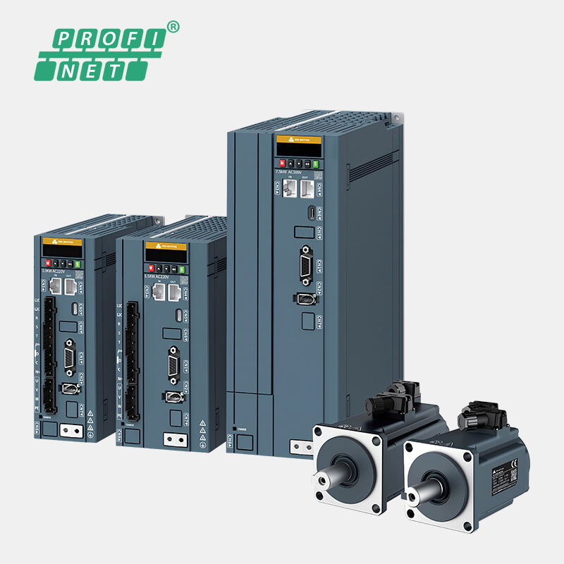

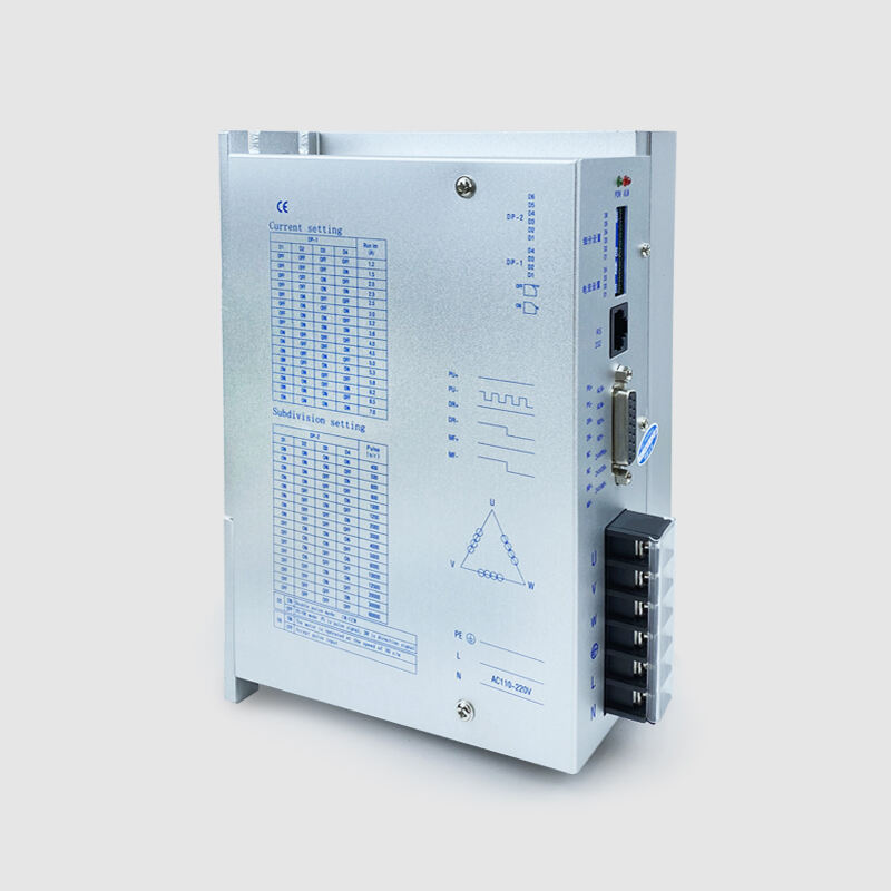
Our STD3722 is a digital stepper motor driver based on DSP control. The stepper motors driven by STD3722 can run with much smaller noise and much less vibration than other drivers in the market. And the positioning accuracy can reach up to 60,000 steps/revolution. This stepper driver is widely used in large and medium-sized CNC equipment with high resolution such as engraving machines, medium-sized CNC machine tools, computer embroidery machines, and packaging machinery.
1.Features
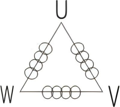
● 3-phase digital stepper driver, adoption of 32-bit DSP technology
● Low-noise, low-vibration and low temperature rising
● Voltage 110v~220VAC
● With 8 stalls output current setting, peak current 7.0A
● With 16 stalls microstep subdivision setting, the highest resolution of 60000 steps / turn
● Automatic half current, self-test, over voltage, under voltage, over current protection
● Internal optical isolation, the highest response frequency of up to 200Kpps
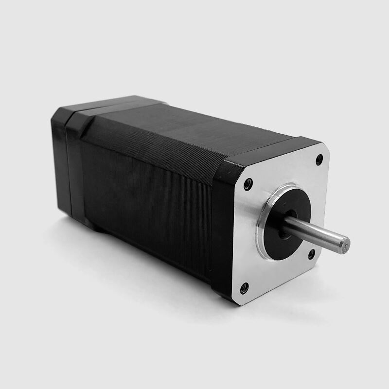
● Suitable for 3-phase nem42 stepper motor, nema 52 stepper motor between1.2-7.0A
● When the step pulse stops for more than 100ms, the coil current is automatically reduced to half of the set current, effectively reducing the motor heat
● Signal voltage : 5V ~ 24V compatible
● Working temperature: -30 ℃~ 85 ℃
2.Microstep Resolution Selection
Pulse/Rev |
D1 |
D2 |
D3 |
D4 |
400 |
ON |
ON |
ON |
ON |
500 |
ON |
ON |
ON |
OFF |
600 |
ON |
ON |
OFF |
ON |
800 |
ON |
ON |
OFF |
OFF |
1000 |
ON |
OFF |
ON |
ON |
1200 |
ON |
OFF |
ON |
OFF |
2000 |
ON |
OFF |
OFF |
ON |
3000 |
ON |
OFF |
OFF |
OFF |
4000 |
OFF |
ON |
ON |
ON |
5000 |
OFF |
ON |
ON |
OFF |
6000 |
OFF |
ON |
OFF |
ON |
10000 |
OFF |
ON |
OFF |
OFF |
12000 |
OFF |
OFF |
ON |
ON |
20000 |
OFF |
OFF |
ON |
OFF |
30000 |
OFF |
OFF |
OFF |
ON |
60000 |
OFF |
OFF |
OFF |
OFF |
3.Current Setting
Current |
D1 |
D2 |
D3 |
D4 |
1.2A |
OFF |
OFF |
OFF |
OFF |
1.5A |
OFF |
OFF |
OFF |
ON |
2.0A |
OFF |
OFF |
ON |
OFF |
2.3A |
OFF |
OFF |
ON |
ON |
2.5A |
OFF |
ON |
OFF |
OFF |
3.0A |
OFF |
ON |
OFF |
ON |
3.2A |
OFF |
ON |
ON |
OFF |
3.6A |
OFF |
ON |
ON |
ON |
D5: ON, double pulse: PU is forward step pulse signal, DR is reverse step pulse signal; OFF, single pulse: PU is the step pulse signal, DR is the direction control signal
D6: automatic detection switch (OFF when receiving external pulse, ON the drive to the internal speed of 30 r / min)
4.Signal Ports (DB15) Description
Port definition |
Pin number |
Symbol |
Features |
Annotations |
RS-232 |
1 |
RX |
Receive data |
Connected to the controller port TX (function retained) |
2 |
TX |
Send data |
Connected to the controller port RX (function retained) |
|
8 |
GND |
Ground line |
Connected to the controller port ground line (function retention) |
|
|
DB15 |
1 |
PU+ |
Input pulse signal positive terminal |
connect the signal power supply, +5V~+24V can be driven |
2 |
PU- |
DP5=OFF, PU is step pulse signal |
The falling edge is valid. When the pulse goes from high to low, the motor takes a step, and the internal current limiting resistor 220Ω requires: low level 0~0.5V, high level 24V or less, pulse width 2.5μS |
|
DP5=ON, PU is positive phase step pulse signal | ||||
3 |
DR+ |
Input direction signal positive terminal |
connect the signal power supply, + 5V~ +24V can be driven |
|
4 |
DR- |
DP5=OFF, DR is direction pulse signal |
Used to change the motor steering. Requirements: low level 0-0.5V, high level 24V or less, pulse width 2.5μS |
|
DP5=ON, DR is reverse pulse signal | ||||
|
5 |
MF+ |
Input motor release signal (enable signal) positive terminal |
connect the signal power supply, +5V~+24V can be driven |
|
|
6 |
MF- |
Motor release signal (enable signal) negative terminal |
When motor is off power and driver stop working, the motor is in free state |
|
7 |
NC |
|
invalid |
|
8 |
NC |
|
invalid |
|
9 |
ALM+ |
Fault output signal positive terminal |
over current, over heating alarm |
|
10 |
ALM- |
Fault output signal negative terminal |
|
|
11 |
RDY+ |
Ready output signal positive terminal |
Indicate the driver is ready to work |
|
12 |
RDY- |
Ready output signal negative terminal |
|
|
13, 14, 15 |
NC |
|
invalid |
|
Motor, power supply side |
1,2 |
L,N |
Power supply |
110v ~ 220v |
3 |
PE |
Ground line |
Earth (built-in drive housing) |
|
4 |
U |
Motor lines |
|
|
5 |
V |
|||
6 |
W |
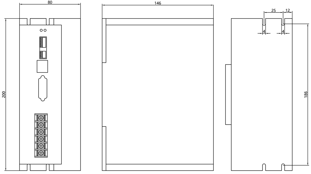
5.Overall Dimensions
6.Custom Service
We provide a variety of customization options in the design, such as output shaft type, connectors, brakes, encoders and gearboxes, etc. Users can flexibly choose according to actual needs. Also can be designed & manufactured with special customized request.
7.Options
Wires |
Flange |
Shaft |
Screw |
|
|
|
|
Encoder |
Brake |
Gearbox |
And More |
|
|
|
+ |
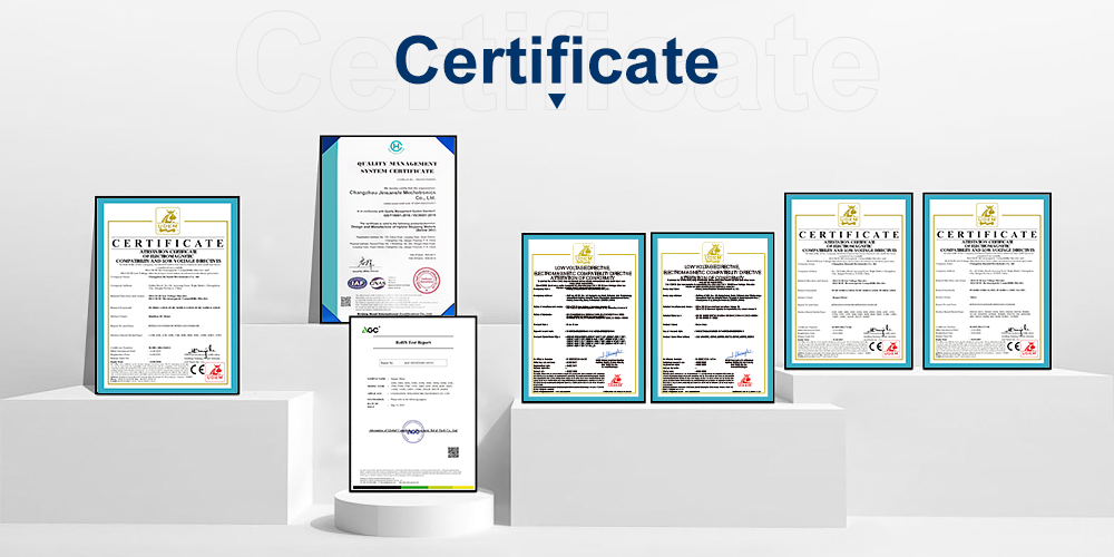
8.Certificate
We have passed the ISO-9001 quality certification system and obtained a number of application patents. Our products have international certifications such as CE and ROHS.
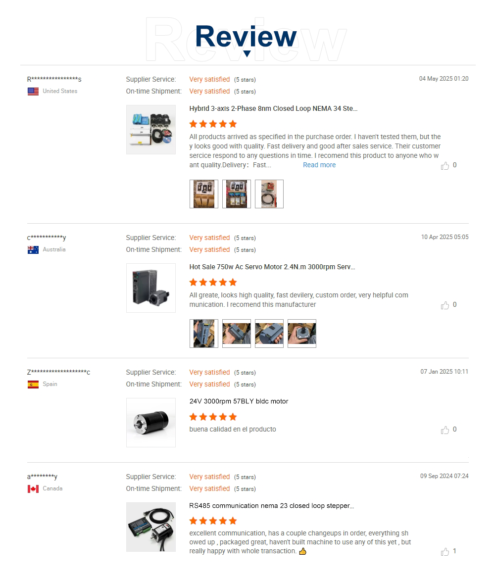
9.Review
Copyright © 2026 Changzhou Jinsanshi Mechatronics Co., Ltd. All rights reserved. - Privacy policy