
Home > Products > Closed Loop Steppers Motors & Drivers > Closed Loop Stepper Driver
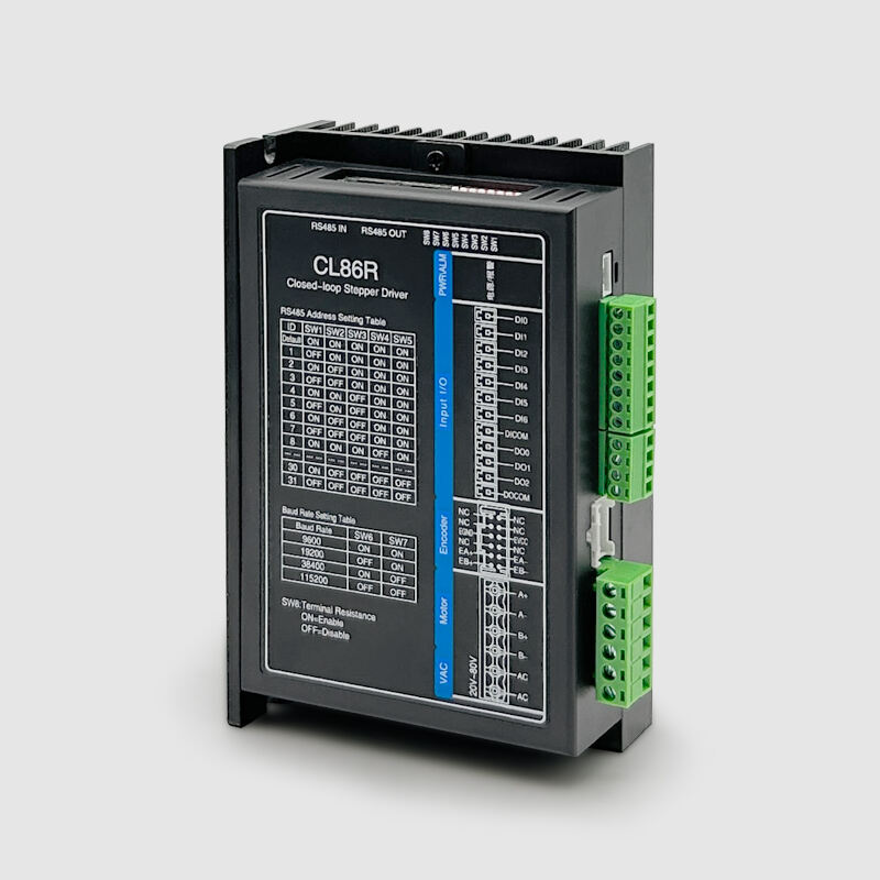
CL86R Is a RS485 bus based support Modbus RTU protocol, closed-loop step driver product. The product integrates the function of single-axis controller, standard Modbus RTU bus communication protocol, the maximum available mount 32 axes, multi-axis bus synchronous control, the drive with position control, speed control, internal position and 16 internal speed control, support zero, absolute / relative positioning, JOG, can directly use touch screen or controller with RS485 interface control.
1.Features
● Support the standard Modbus RTU protocol on the RS485 bus;
● Do not lose the step, accurate positioning;
● The current is adjusted according to the load to adapt to various mechanical load conditions;
● Built-in acceleration and deceleration and smooth filtering control, smoother operation;
● User-defined fine score;
● Support position, speed, return to zero, JOG, multiple position, multiple speed and other modes;
● 7 input ports, 3 output port functions can be programmable configuration;
● Voltage range: AC20V~80V;
● With over-current, over-pressure, position over-difference and other protection;
2.Typical Application
Suitable for various small and medium-sized automation equipment and instruments, such as industrial robots, textile machinery, special industrial sewing machines, wire stripping machines, marking machines, cutting machines, laser phototypesetting, plotters, CNC machine tools, engraving machines, automatic assembly equipment, etc. The application effect is particularly good in equipment where users expect low noise and high speed.
3.Electrical Indicators
Power Supply Voltage |
AC 20~80V |
output |
Peak value of 8.0A (current changes with load) |
DI input currenton |
10~50mA |
DI input voltage |
+24VDC |
Communication type |
RS485 |
Maximum communication rate |
115200bp s |
4.Environment Parameter
Cooling method |
Natural cooling or external radiator |
|
Usage environment |
Use occasions |
Try to avoid dust, oil and corrosive gases |
Temperature |
0~40℃ |
|
Humidity |
40~90%RH |
|
Vibration |
5.9m/s²Max |
|
Storage temperature |
-20℃~80℃ |
|
5.Power input port
Terminal number |
Symbol |
Name |
Explain |
1 |
AC1 |
AC1 |
AC20V ~80V |
2 |
AC2 |
AC2 |
6.Motor port
Pin |
Signal definition |
Explain |
1 |
A + |
Motor winding A is phase positive |
2 |
A - |
Motor winding A is phase negative |
3 |
B + |
Motor winding B is phase positive |
4 |
B- |
Motor winding B is phase negative |
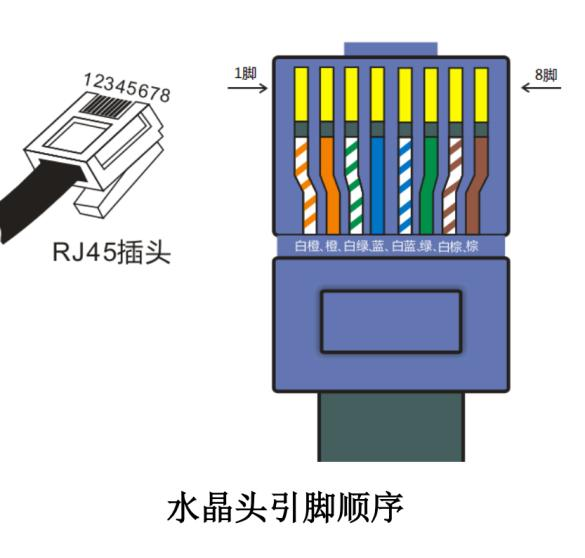
7.RS485 communication port
Pin |
Signal definition |
Network cable color |
1 |
RS 485+ |
white and orange |
2 |
RS 485- |
orange |
3 |
NC |
white and green |
4 |
NC |
blue |
5 |
GND |
white and blue |
6 |
GND |
green |
7 |
NC |
white and brown |
8 |
NC |
brown |
8.Encoder port
Pin |
Definition |
Illustrate |
1 |
SHIELD |
Encoder shield |
2 |
NC |
RS485- |
3 |
NC |
|
4 |
NC |
|
5 |
EVCC |
Main end of the encoder power supply |
6 |
EGND |
Encoder power supply negative end |
7 |
NC |
|
8 |
NC |
|
9 |
EB+ |
|
10 |
EB- |
|
11 |
EA+ |
|
12 |
EA- |
|
9.DI/DO port
Terminal number |
Symbol definition |
Illustrate |
1 |
DI0 |
Single-ended input port: valid working voltage 24V |
2 |
DI1 |
|
3 |
DI2 |
|
4 |
DI3 |
|
5 |
DI4 |
|
6 |
DI5 |
|
7 |
DI6 |
|
8 |
DICOM |
Input port common port: compatible with common anode and common cathode connection method |
9 |
DO0 |
Single-ended output port |
10 |
DO1 |
|
11 |
DO2 |
|
12 |
DOCOM |
Output port common port: negative pole of power supply |
10.Status indication
PWR: Power Indicator light. When power is on, the green indicator is always on.
ALM: Fault indicator light. The red light flashes once within 3 seconds: over-current or inter-phase short-circuit fault; The red light flashes for 2 times within 3 seconds: over-voltage fault ; The red light flashes 7 times within 3 seconds : position error error alarm.
11.DIP switch setting
CL86R use the 5-bit dial switch to set the drive station number and the 2-bit dial switch to set the communication wave rate.
SW1-SW5 : Drive station number is set. SW6 to SW7 : Drive communication Baud rate. From the station number, the communication port rate needs to be modified again.
From the station number |
SW1 |
SW2 |
SW3 |
SW4 |
SW5 |
Default |
ON |
ON |
ON |
ON |
ON |
1 |
OFF |
ON |
ON |
ON |
ON |
2 |
ON |
OFF |
ON |
ON |
ON |
3 |
OFF |
OFF |
ON |
ON |
ON |
4 |
ON |
ON |
OFF |
ON |
ON |
5 |
OFF |
ON |
OFF |
ON |
ON |
6 |
ON |
OFF |
OFF |
ON |
ON |
7 |
OFF |
OFF |
OFF |
ON |
ON |
8 |
ON |
ON |
ON |
OFF |
ON |
9 |
OFF |
ON |
ON |
OFF |
ON |
10 |
ON |
OFF |
ON |
OFF |
ON |
11 |
OFF |
OFF |
ON |
OFF |
ON |
12 |
ON |
ON |
OFF |
OFF |
ON |
13 |
OFF |
ON |
OFF |
OFF |
ON |
14 |
ON |
OFF |
OFF |
OFF |
ON |
15 |
OFF |
OFF |
OFF |
OFF |
ON |
16 |
ON |
ON |
ON |
ON |
OFF |
17 |
OFF |
ON |
ON |
ON |
OFF |
18 |
ON |
OFF |
ON |
ON |
OFF |
19 |
OFF |
OFF |
ON |
ON |
OFF |
20 |
ON |
ON |
OFF |
ON |
OFF |
21 |
OFF |
ON |
OFF |
ON |
OFF |
22 |
ON |
OFF |
OFF |
ON |
OFF |
23 |
OFF |
OFF |
OFF |
ON |
OFF |
24 |
ON |
ON |
ON |
OFF |
OFF |
25 |
OFF |
ON |
ON |
OFF |
OFF |
26 |
ON |
OFF |
ON |
OFF |
OFF |
27 |
OFF |
OFF |
ON |
OFF |
OFF |
28 |
ON |
ON |
OFF |
OFF |
OFF |
29 |
OFF |
ON |
OFF |
OFF |
OFF |
30 |
ON |
OFF |
OFF |
OFF |
OFF |
31 |
OFF |
OFF |
OFF |
OFF |
OFF |
Note : the slave number setting, when in default, can be defined by setting a custom drive slave off register (0x0020) from 1 to 31.
Communication Porter Rate |
SW6 |
SW7 |
9600 |
ON |
ON |
19200 |
OFF |
ON |
38400 |
ON |
OFF |
115200 |
OFF |
OFF |
Note : When the communication port rate is set to 9600bp s, the serial port data format is fixed to 8 data bits, no check, and 1 stop bit. When set to the other three aud rates, the serial port data format is determined by the serial port data format register (0x0021).
SW8: RS485 terminal resistance, the bus end drive shall set the dial switch to ON, and the rest drive shall be set to OFF.
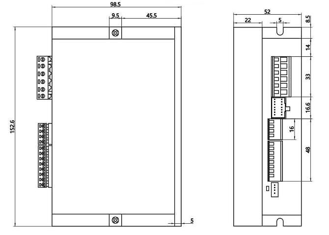
12.Overall Dimensions(unit=mm)
13.Custom Service
We provide a variety of customization options in the design, such as output shaft type, connectors, brakes, encoders and gearboxes, etc. Users can flexibly choose according to actual needs. Also can be designed & manufactured with special customized request.
14.Options
Wires |
Flange |
Shaft |
Screw |
|
|
|
|
Encoder |
Brake |
Gearbox |
And More |
|
|
|
+ |
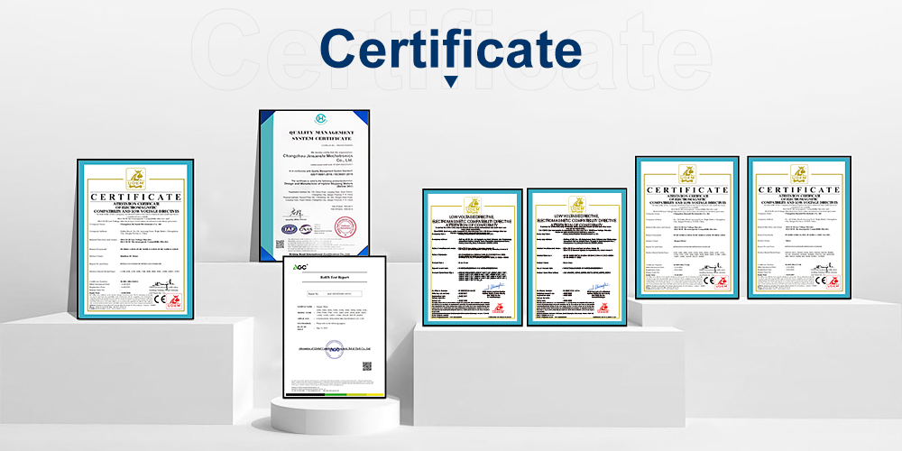
15.Certificate
We have passed the ISO-9001 quality certification system and obtained a number of application patents. Our products have international certifications such as CE and ROHS.
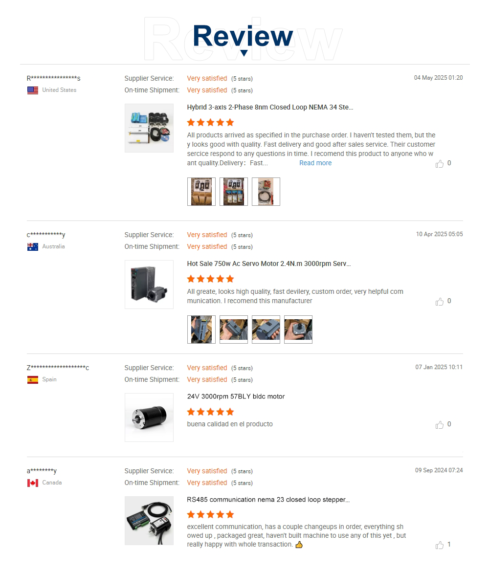
16.Review
Copyright © 2026 Changzhou Jinsanshi Mechatronics Co., Ltd. All rights reserved. - Privacy policy