
Home > Products > Integrated Stepper Servo Motors > RS485 Integrated Stepper Servo Motors
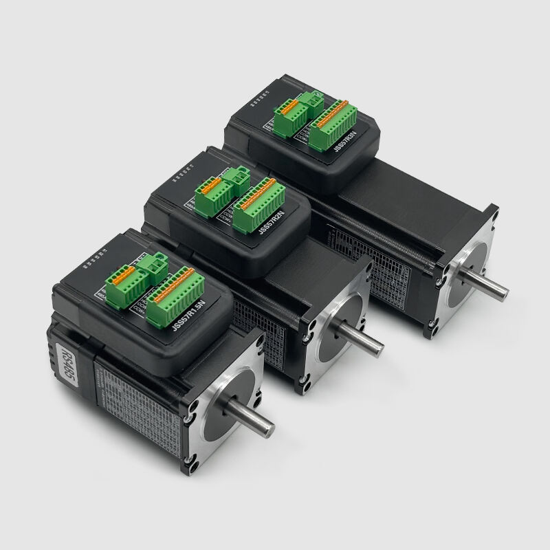
Our JSS57R is an integrated hybrid servo motors based on RS485 bus that supports Modbus RTU protocol. This product integrates the hybrid servo motor and the driver, and uses the standard Modbus RTU bus communication protocol for control. Compared with the traditional combination of stepper motor driver and stepper motor, the cost performance is higher. This integrated hybrid servo product integrates the advantages of bus communication control, simple wiring, no lost steps, low temperature rise, low noise, high speed, high torque, and low cost. It is a very cost-effective motion control product.
1.Features
2.Electrical specifications
Model No. |
Step Angle |
Motor Length |
Current /Phase |
Resistance /Phase |
Inductance /Phase |
Holding Torque |
( °) |
(L)mm |
A |
Ω |
mH |
N.m |
|
JSS57R1.5N |
1.8 |
56 |
4.2 |
0.4
|
1.2 |
1.2 |
JSS57R2N |
1.8 |
76 |
4.2 |
0.5 |
1.8 |
2 |
JSS57R3N |
1.8 |
112 |
4 |
0.9 |
4.0 |
3 |
3.Electrical indicators
Power supply |
DC24~48V, Recommended power supply DC36V |
Output current |
Peak 6.0A (current varies with load) |
Logic input current |
7~16mA, 10mA recommended |
Communication type |
RS485 |
maximum communication rate |
115200bps |
Power supply |
DC24~48V, Recommended power supply DC36V |
5.Usage environment and parameters
Cooling method |
Natural cooling or external radiator |
|
Use environment |
Use occasions |
Avoid dust, oil and corrosive gases as much as possible |
Temperature |
0~40℃ |
|
Humidity |
40~90%RH |
|
Vibration |
5.9m/s²Max |
|
Storage temperature |
-20℃~80℃ |
|
6.Interface definition
(1)Power input port
Terminal number |
Symbol |
Name |
Illustrate |
1 |
+Vdc |
DC power positive terminal |
DC+24V~48V Recommended DC+36V power supply |
2 |
GND |
DC power ground |
(2)Control signal port
Terminal number |
Symbol |
Name |
Illustrate |
1 |
CCW+ |
Positive limit positive |
Support +5V~+24V |
2 |
CCW- |
Positive limit negative |
|
3 |
HOME+ |
The mechanical origin is positive |
|
4 |
HOME- |
Negative mechanical origin |
|
5 |
CW+ |
Negative limit positive |
|
6 |
CW- |
Negative limit negative |
|
7 |
PEND+ |
In-position signal positive output |
|
8 |
PEND-- |
In-position signal negative output |
|
9 |
ALM+ |
Alarm signal is outputting |
|
10 |
ALM- |
Alarm signal negative output |
(3)RS485 communication port
Terminal number |
Symbol |
Name |
1 |
RS485+ |
RS485 communication interface |
2 |
RS485- |
|
3 |
RS485+ |
|
4 |
RS485- |
|
5 |
GND |
|
(4)Status indication
PWR: Power Indicator. When powered on, the green indicator light is always on.
ALM: Fault indicator. Red light flashes once within 3 seconds: over-current or phase-to-phase short circuit fault; The re times light flashes 2 times continuously within 3 seconds: Over-voltage fault;
The red light flashes 7 times continuously within 3 seconds: the position error is out of tolerance alarm.
7.DIP switch setting
JSS57R uses a 6-bit DIP switch to set the drive station number and communication baud rate.
SW1~SW4: Drive station number setting. SW5~SW6: Drive communication baud rate. After the slave station number and communication baud rate are modified, it needs to be powered on again to take effect.
Slave number |
SW1 |
SW2 |
SW3 |
SW4 |
default |
ON |
ON |
ON |
ON |
1 |
OFF |
ON |
ON |
ON |
2 |
ON |
OFF |
ON |
ON |
3 |
OFF |
OFF |
ON |
ON |
4 |
ON |
ON |
OFF |
ON |
5 |
OFF |
ON |
OFF |
ON |
6 |
ON |
OFF |
OFF |
ON |
7 |
OFF |
OFF |
OFF |
ON |
8 |
ON |
ON |
ON |
OFF |
9 |
OFF |
ON |
ON |
OFF |
10 |
ON |
OFF |
ON |
OFF |
11 |
OFF |
OFF |
ON |
OFF |
12 |
ON |
ON |
OFF |
OFF |
13 |
OFF |
ON |
OFF |
OFF |
14 |
ON |
OFF |
OFF |
OFF |
15 |
OFF |
OFF |
OFF |
OFF |
Note: The slave station number setting, when it is in the default file, can define the slave station number by setting the custom drive slave station number register (0x0020), the range is 1~31.
Communication baud rate |
SW5 |
SW6 |
9600 |
ON |
ON |
19200 |
OFF |
ON |
38400 |
ON |
OFF |
115200 |
OFF |
OFF |
Note: When the communication baud rate is set to 9600bps, the serial data format is fixed to 8 data bits, no parity, and 1 stop bit. When set to other three baud rates, the serial port data format is determined by the serial port data format register (0x0021).
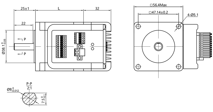
8.Overall Dimensions
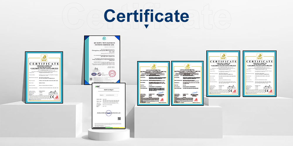
9.Certificate
We have passed the ISO-9001 quality certification system and obtained a number of application patents. Our products have international certifications such as CE and ROHS.
10.Review

Copyright © 2026 Changzhou Jinsanshi Mechatronics Co., Ltd. All rights reserved. - Privacy policy