
Introduction to NEMA 23 Stepper Motors
NEMA 23 stepper motors combine good torque with pretty decent precision, which is why they show up so much across different industries. When we talk about NEMA 23, what we're really referring to is the physical size of the motor frame itself, measuring around 2.3 by 2.3 inches. This standard sizing helps these motors fit into all sorts of mechanical configurations without too much hassle. At their core, these motors work through electromagnetic fields, something anyone working with them should understand before trying to wire things up properly. Because of how consistently they perform, many manufacturers rely on NEMA 23 motors for tasks in robotics, CNC machines, and even 3D printers where getting things positioned just right matters a lot for the final product quality.
Getting the wiring right makes all the difference when it comes to getting the most out of these motors. Good wiring practices ensure things run smoothly without unexpected problems down the line. When installed properly, the motor will work better for longer periods of time while maintaining its efficiency levels. For anyone working with NEMA 23 stepper motors in industrial settings or automation systems, proper installation matters a lot. These motors deliver impressive results when everything from the connections to the mounting is done just right according to manufacturer specifications.
Identifying Motor Type: Bipolar vs. Unipolar
Differences Between Bipolar and Unipolar Stepper Motors
Bipolar stepper motors come with two coils and need more complicated driver circuits, something that actually gives them better torque and overall efficiency. Because of this, these motors work really well in situations where top notch performance matters most, like when building precision robots or running heavy duty industrial machines. On the flip side, unipolar steppers usually have either four or five wires total, so they can run on much simpler circuitry setups. But there's a trade off here too since these motors generally don't perform as strongly as bipolar ones do. Getting the wiring right depends heavily on knowing whether we're dealing with bipolar or unipolar configurations. For anyone trying to pick the right motor for their project, understanding how many wires each type requires becomes absolutely essential to avoid headaches down the road.
Impact of Wiring Configuration on Torque and Efficiency
How a stepper motor is wired makes all the difference in how much torque it can produce and how efficient it runs. Bipolar motors tend to deliver better torque since they use both coils completely. When both coils work together, the motor can push harder, which is why many industrial applications rely on bipolar setups for heavy lifting tasks. Unipolar motors take a different approach by only using one coil at a time. While this makes controlling them simpler, especially for hobbyists or basic automation projects, it comes at the cost of reduced energy efficiency. For anyone selecting a stepper motor for their system, understanding these wiring differences matters a lot. The right choice depends not just on what kind of power is needed, but also factors like budget constraints and whether maintenance access will be easy down the road.
Understanding Wire Color Codes
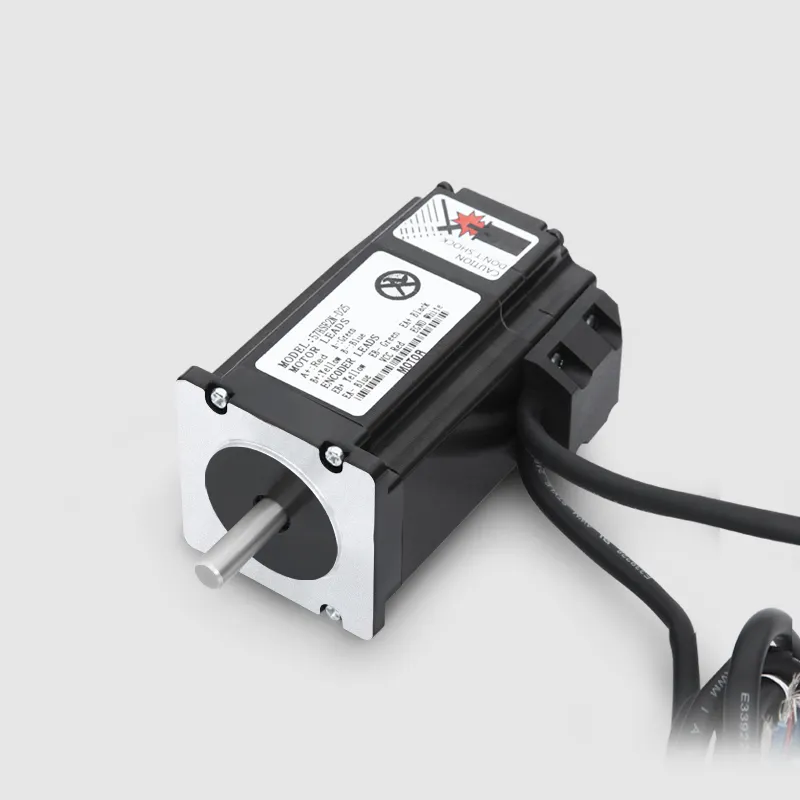
Getting familiar with wire color codes makes all the difference when it comes to proper wiring and keeping stepper motors running safely. Most companies stick to standard color codes to make things easier during installation, typically working with red, black, green, blue and sometimes yellow wires. But here's the catch nobody tells beginners: always check the manufacturer's datasheet before connecting anything because color schemes do differ between brands occasionally. Real technicians know this stuff from experience rather than theory books. Those datasheets really cut down on mistakes that could lead to dangerous situations or damaged equipment. Knowing what each colored wire does is basically step one if someone wants their NEMA 23 stepper motor setup to work right. These motors power everything from factory automation lines to precision robotics systems across industries today.
How to Use a Multimeter to Determine Coil Pairs
Getting accurate connections can be tricky, especially when facing those confusing non-standard color codes. That's where a good multimeter comes in handy. By checking resistance between motor wires, we can actually figure out which ones belong together in the same coil. During tests, if two wires come from the same coil, they'll show pretty low resistance readings. But connect wires from different coils and suddenly the resistance jumps way up. This simple test really pays off because it stops those frustrating wiring mistakes before they happen and keeps motors running smoothly. Anyone who works with stepper motors should master this basic technique with a multimeter. It makes all the difference when color codes don't match what's expected, helping maintain top performance no matter what.
Connecting to a Stepper Driver
Matching Motor Wires with the Driver Terminals
Getting those stepper motor wires connected properly to the driver terminals really matters if we want things to work right. Most of the time folks just match up the motor wires with the A+, A-, B+, and B- spots on the driver board. Knowing how these terminals are laid out and what each one does makes life a lot easier when hooking everything together. Before diving in though, it's smart to check out whatever paperwork came with the equipment or look at any labels they might have put on there. I've seen plenty of headaches come from skipping this step. Taking a few minutes extra upfront saves time later on, both in terms of avoiding wasted effort and preventing possible damage to motors from wrong connections.
Importance of Correct Phase Alignment to Prevent Malfunction
Getting the phases properly aligned matters a lot when it comes to making sure motor coils get powered in just the right order for smooth spinning action. When phases aren't lined up correctly, motors tend to stall out or move around unpredictably, which really messes with how well they work overall. If technicians want to prevent these kinds of problems, having good visual references or those detailed wiring charts makes all the difference in connecting things right. Motors that have their phases set correctly run better, last longer between breakdowns, and generally perform without hiccups during normal operations. Most electricians will tell anyone who asks that taking time to check phase alignment saves headaches down the road.
Setting Proper Voltage and Current
Ensuring Power Supply Meets Motor Requirements
Getting the right power supply that matches the voltage and current needs of a NEMA 23 stepper motor matters a lot for how well it works. Most of these motors need certain voltage levels and current amounts specified by their manufacturers. When we follow those specs, we avoid problems like poor performance or the motor getting too hot. Always check what the maker says about power requirements because they know best what their product needs to run properly. Skip reading those specs at your own risk since wrong power settings often result in motors running inefficiently or burning out faster than expected. We've seen this happen plenty of times when people try to cut corners on electrical connections.
Adjusting Driver Settings for Optimal Performance and Heat Management
Tweaking driver settings makes all the difference when it comes to getting the most out of stepper motors while keeping them from overheating. Nearly every driver on the market has options to control how much current flows through the motor, something that directly affects both heat buildup and how long the motor will last before needing replacement. When drivers are set up right, they deliver better torque without generating so much heat during normal operation. Motor enthusiasts often keep an eye on these parameters as they run their systems, catching problems before they become serious headaches. Regular monitoring lets technicians find the sweet spot where performance stays strong but temperatures stay within safe limits, ultimately saving money on repairs and extending the useful life of expensive motor equipment.
Testing and Troubleshooting
Checking Motor Rotation Direction and Adjusting if Needed
Once the NEMA 23 stepper motor gets wired up, checking how it actually spins should be step one on anyone's list. The rotation needs to match what the machine was designed for otherwise things just won't work right. When the motor turns the wrong way around, most folks fix this by swapping any pair of wires connected to it. That simple trick flips the direction completely. Before touching anything though, take a good look at all those connections again. Double checking saves time later when trying to figure out why something isn't working properly. Getting the rotation sorted out early helps everything run smoothly from day one without messing up the whole setup down the road.
Identifying Common Wiring Issues and Resolving Them
Wiring problems happen all the time in motor systems. Things like loose connections, wrong setups, or even short circuits will definitely mess up how well a motor works. When trying to fix these kinds of issues, going through connections one at a time tends to work best. Most technicians find this method saves them tons of time hunting around blindly. A good idea is to make a simple list of what needs checking during tests. This helps catch problems faster before they become bigger headaches later on. The main benefit here isn't just about saving time though. Proper wiring actually makes motors last longer because everything runs smoother when everything's connected right from the start.
Conclusion
Getting the wiring right makes all the difference when it comes to how well NEMA 23 stepper motors run and last over time in things like industrial automation or robotics. When connections are properly secured and set up correctly, this affects both what happens right away with the motor performance and how long it will keep working reliably. Testing regularly and making adjustments when needed helps get the most out of these motors without having them sit idle for repairs. If companies take care of their motor systems before problems happen, they avoid those frustrating breakdowns that disrupt production lines, assembly plants, and other facilities relying on these motors day after day. Doing maintenance work ahead of time pays off in better efficiency now and supports longer lasting equipment operation down the road.
FAQs
What does NEMA 23 mean?
NEMA 23 refers to the size of a stepper motor's frame, measuring 2.3 x 2.3 inches, which ensures compatibility with various mechanical setups.
What is the difference between bipolar and unipolar stepper motors?
Bipolar motors have two coils and offer higher torque and efficiency, requiring more complex driver circuits. Unipolar motors have simpler circuits with four or five wires but provide lower performance.
How can I determine the correct coil pairs in a stepper motor?
A multimeter is used to measure resistance across motor wires. Wires from the same coil show low resistance, while those from different coils indicate high resistance.
Why is phase alignment important in stepper motors?
Phase alignment ensures that motor coils are energized in the correct sequence for smooth rotation, preventing operational malfunctions like stalling.
How do I reverse the rotation direction of a stepper motor?
To reverse the rotation, swap any two wires of the motor; this will change the rotation direction effectively.